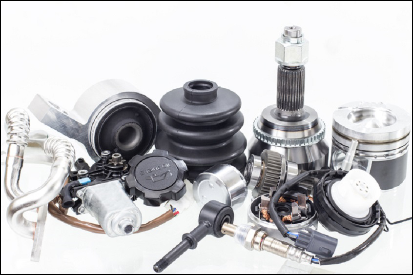
The quality of the component is in part determined by its pressure or leak integrity. Some examples of components include the fuel tank, oil and fuel filters, radiator, air conditioning and heating system components, manifolds, gear cases, hoses and more. Prior to delivering parts to the auto manufacturer, the component part supplier is often required to test and/or document the component’s quality.

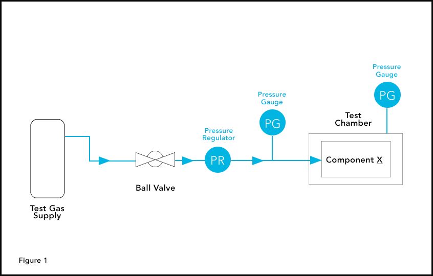
A leading manufacturer of fuel filters wanted to improve the productivity and efficiency of their quality control testing process. They were previously utilising a differential pressure method to leak test the fuel filters. The process required a pressurised filter be placed in a test chamber. The air surrounding the filter inside the chamber was then monitored for an increase in pressure. If an increase in pressure was present, this would indicate leakage from the filter (See Figure 1). The approach was slow, inefficient and generated unnecessary waste.

Application Requirements
The goal of the new testing process would improve speed and efficiency by eliminating three key issues.
- Test results were subject to multiple variables and prone to inaccuracies. For example, residual heat would get introduced into a filter and become trapped, thus throwing off the pressure readings.
- Test outcomes were provided simply as pass/fail, with no additional data to help isolate the failure source and to facilitate continuous process improvement.
- The process required intense manual operation. These factors lead to high retest rates and false fails, resulting in the rejection of good parts.
Highlights
- Improve filter leak test accuracy and efficiency
- Reduce the labour requirement
- Increase productivity and throughput
Process Solution
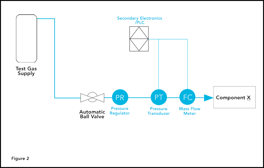
For this unique set of challenges, a mass flow leak testing approach was the solution. This method simplifies testing by measuring the flow and eliminating the testing chamber from the equation. As shown in Figure 2, the Brooks Instrument SLA5860 thermal mass flow metre is at the heart of the automated leak detection process. The system also includes a PLC, automated ball valve, and the Brooks Instrument Solid Sense II pressure transducer. For each test cycle, the supply line is pressurised, the air moves thru the system to the component being tested, and the flow is measured. It takes less than a second for the precise amount of leakage to be determined, with an accuracy of ±0.9% of SP. To help reduce cycle times, piping and system overall volumes were minimised. To help achieve this, helium gas should be used, since it is the smallest molecule and is more prone to leak vs a larger molecule. However, due to the rising costs of helium, the manufacturer may use clean dry compressed air or nitrogen instead.

The reduced response time and overall process efficiencies have allowed throughput to more than double. By eliminating the chamber from the process and some manual operations, labour has been reduced. With this leak testing approach, the system provides a documented leak level that can be used for SPC in addition to the pass/fail indication. It also allows the the operator to determine the source of the leak with a secondary operation. This all adds up to increased quality, throughput and profitability.
This highly efficient and accurate mass flow leak testing method can be employed for virtually any automotive component that retains pressure or has flow thru it.
Depending on the specific application, the solution may contain one or more instruments and components including the Brooks Instrument Mass Flow Metre (SLA5860), Solid Sense II pressure transmitter, Secondary Electronics (0251 or 0254), Mechanical Pressure Regulators (8601), or a Pressure Gauge (S122).